November 15, 2026 · 10 min read
Plumbing and Electrical Plan for Cabinets: Print It Instantly
The water, drain, gas, socket and hood duct points you place while drawing the kitchen turn into a dimensioned sheet for the installer. Back panel cut-outs come out on their own.
The most expensive surprise on a kitchen install is pushing a cabinet against the wall and finding a water valve or a socket right behind it. The plumber ran it at the height he always uses, you built the cabinet to your drawing, and now someone is cutting the back panel with a jigsaw on site, or the cabinet goes back to the shop. In CabinetWizard, service points are part of the kitchen plan. The moment you place a point on a wall, the program works out which cabinet's back panel gets cut and where, and a dimensioned drawing for the installer is ready. This article covers what that services drawing shows and how it's used in the shop.
Why is the services plan the cabinet maker's job?
In most homes the order goes like this: the plumber and electrician come first, the cabinet maker second. The trades rarely have the cabinet plan in hand, so water comes out "where it usually goes" and sockets end up "somewhere above the counter". You are the one who knows the plan. If you drew where the sink base, the dishwasher and the hob go, you're the right person to say where the services should come out. The services drawing exists for exactly that: it writes your plan in the installer's language, meaning wall, distance and height.
It works the other way too. If you're drawing cabinets on a wall where the services are already in, you measure the points and enter them; the program places the cabinets around them and calculates the cut-outs. So the drawing goes both directions: it either tells the installer what to do, or it carries existing services into the cabinets.
Which service points can you place?
The kitchen plan has five service types: water, drain, gas, socket and hood duct outlet. Each point belongs to a wall and is defined by three values: which wall, how many mm from the left, how many mm from the floor. You can drag a point with the mouse or type it in mm, and the drawing tools let you place it straight in the 3D view. The starting values the program offers are only suggestions; the real measurement is something the installer or fitter should type in for every point.
In 3D the points show up as real models: a socket (double or triple), a water valve, a drain outlet, a gas valve. They're included in renders too, so the image you show the client already tells them where the socket will sit above the worktop. If you've clad a wall in panels and a point ends up behind the panel, the point moves out into the room by the panel thickness, so the socket shows in front of the panel.
The hood duct outlet and its diameter
The hood duct outlet, the hole where the extractor duct leaves through the wall or ceiling, is a round service point. You pick its diameter from the Ø chips, and the "centre on hood" button moves it to the middle of the hood module. On the drawing it's a circle with the diameter written next to it (Ø150, for example). If the outlet lands on a beam, the program doesn't drill the beam: the duct runs straight down to the underside of the beam, makes an S with two 45° elbows in front of it, and goes up to the ceiling from there. The drawing marks that S path. The hood duct outlet is available in every room type, not only kitchens.
What does the services drawing show?
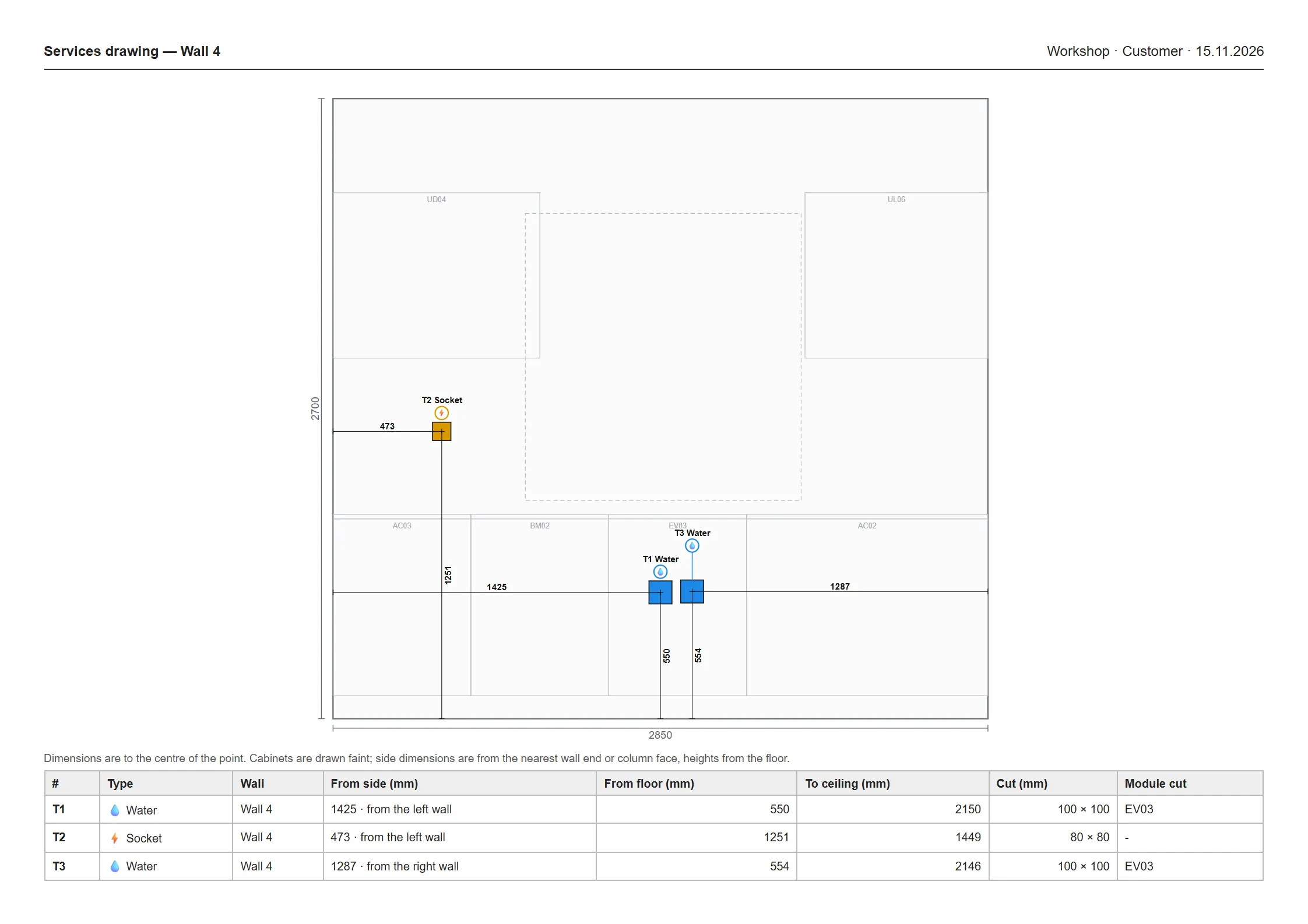
The kitchen plan's Output section includes a services drawing. The program draws a separate A4 landscape page for every wall that has a service point on it. Cabinets are drawn faint, service points dark and numbered T1, T2, T3. The installer sees where the cabinets will go, but the eye stays on the points.
Every point gets two dimensions. The side dimension is taken from the nearest wall end or column face; the height is from the floor. Dimensions are to the centre of the point. The installer hooks the tape on the nearest corner, measures up from the floor, marks it, and doesn't need to work anything out.
Example: a 2850 mm sink wall
The drawing above is wall 4 of our sample kitchen: 2850 mm long with a 2700 mm ceiling. The base row holds modules AC03, BM02, EV03 and AC02, with UD04 and UL06 above. The table has three rows:
| # | Type | From side (mm) | From floor (mm) | To ceiling (mm) | Cut (mm) | Module cut |
|---|---|---|---|---|---|---|
| T1 | Water | 1425 · from the left wall | 550 | 2150 | 100 × 100 | EV03 |
| T2 | Socket | 473 · from the left wall | 1251 | 1449 | 80 × 80 | – |
| T3 | Water | 1287 · from the right wall | 554 | 2146 | 100 × 100 | EV03 |
Notice that T3 is dimensioned from the right wall, because that's the nearest end for that point. The T2 socket sits above the worktop, so it doesn't cut any cabinet and the last column shows a dash. Both water points fall behind the sink base EV03, so the program opens two 100 × 100 cut-outs in that cabinet's back panel. The installer reads the table; you read the same table to know which back panel gets cut. Download the sample: Services drawing sample (PDF).
Do the back panel cut-outs appear automatically?
Yes. When a service point lands behind a cabinet, the back panel cut-out is stored as a calculation, not a saved shape: move the cabinet, move the point or lengthen the wall and the cut-out is recalculated. This is parametric cabinet design reaching into the services; because the cabinet sizes are parametric dimensions, values that rebuild everything connected when they change, the cut-out moves with the cabinet.
The cut-out is read from the same place in 3D, in NC, in DXF and in the cut list. The cut sizes pages at the end of the kitchen plan output list service cut-outs alongside the sheet parts. Only modules on the same wall as the point are cut; a module without a back panel, such as an appliance housing, isn't cut. If a cut-out would cover the whole back panel, the program doesn't apply it and warns you. If a cabinet sits over a service point, you get a warning as well; click it and you jump to that module. Service cut-outs are counted as notches in the labour calculation.
On the shop floor, that means the back panel comes off the CNC router with the service hole already cut. No saw, no drill, no guessing on site. Error-free CNC cutting comes the same way here: there's no step where a size is carried by hand from one place to another, so there's nowhere for a mistake to get in. The back panel is listed like every other part, with its edge band and grain direction information, meaning which edges get banded and which way the pattern runs.
How does Auto Place use the services?
Service points aren't just for the drawing; they drive the layout too. In the kitchen plan, ⚡ Auto Place reads the services: it puts the sink at the drain and the hob at the gas, and sets the dishwasher on the side that keeps its drain in the sink base. Appliances aren't placed on wall projections. We call this smart kitchen design: planning where the cabinets place themselves around door swings, columns and service points. If you've got a wall with the services already in, entering the points and pressing Auto Place is quicker than arguing about where the sink should go.
The kitchen wizard treats services as their own step. In the fourth question, appliances and services, you choose the sink, the hob (gas or electric) and the fridge; water, drain and gas points come with the appliances. Sockets are suggested, and you can add more by hand. When the wizard finishes, the kitchen is on screen with its services, and the drawing can be printed right away.
From services to production: one project for everything
The services drawing comes out of the same project as every other output. The cut list, an automatic cut list that updates itself when the design changes, includes the back panel cut-outs. The cutting plan does the sheet nesting, placing parts on the board with as little waste as possible, and draws the automatic sheet layout. In the export to CNC step, parts and cut-outs become CNC/DXF and NC files; the DXF opens in whatever CAM software your shop uses. The whole chain runs inside CabinetWizard's own CNC cutting and machining system, so for a shop doing CNC cabinetmaking, the service hole is just another cut on the sheet for the router to handle.
What happens in kitchen cabinetry design when the services change? Say the client wants the hob on another wall. You move the gas point, press Auto Place again, and the cabinets, the worktop cut-out, the back panel cut-outs and the drawing all update together. That's what we mean by dynamic kitchen design: change one value and every drawing and list that depends on it is recalculated. The worktop side works the same way; we cover the worktop sheet in cut list and worktop dimensions.
The program's settings screens behave like a dynamic settings page in the same spirit. For instance, switch on top cabinets in the measurement standard card under Walls and top cabinets line up above the wall and tall units up to the ceiling, while the space above a chimney hood is left empty. Look-and-feel choices such as door styles, the handle or a finish change on the wall cabinets are a separate matter: service points belong to the wall, so they don't move when you change those. And when you drop drag-and-drop modules, ready-made cabinets from the library, onto a wall with a service point, the cut-out is calculated on its own.
Who saves time with this?
The services drawing is one of the most concrete examples of time-saving cabinet design. You measure, enter the points and hand the sheet to the installer. The phone call asking "how far from the left was the socket?", the back panel cut on site and the cabinet that goes back to the shop all disappear. For us, fast cabinet design is as much about getting the drawing to site correctly as it is about drawing quickly.
For a one-person shop or an interior design office, the program works as a cabinet design studio, a workspace where the design, the services plan and the production outputs are prepared on one screen. The quote comes from the same project; for the current price and launch terms, see the pricing section. You can see the program's other outputs in the outputs section.
Frequently asked questions
Is the services drawing available in the demo?
The demo runs for 5 days; you can place service points and see the kitchen in 3D and in renders. Production outputs such as the services drawing, worktop sheet, cut list, NC and DXF are in the full version.
Is the side dimension always from the left wall?
No. It's taken from the wall end or column face nearest to the point, and the table says which side it was measured from ("from the left wall", "from the right wall").
If a socket is above the worktop, does a cabinet get cut?
No. If the point doesn't fall on a cabinet's back panel, no cut-out is made and the "Module cut" column shows a dash.
What if the hood duct outlet lands on a beam?
The beam isn't drilled. The duct runs straight down to the underside of the beam, makes an S with two 45° elbows in front of it and goes up to the ceiling; the drawing shows that S path. For other questions, see 14 key questions about CabinetWizard.
By Ufuk Şen, developer of CabinetWizard