November 15, 2026 · 10 min read
Accurate CNC Cutting for Your Cabinets, Step by Step
A miscut side panel is rarely the machine's fault; it is usually a size copied from paper to a list. We walk through accurate cutting from dimensions to G-code with real shop examples.

The most expensive sound in a cabinet shop is a full sheet going into the dumpster because the CNC router cut it to the wrong size. Most shop owners already know the uncomfortable truth: the machine is rarely the problem. Mistakes happen wherever a dimension gets copied by hand, from the tape measure to a notebook, from the notebook to a cut list, from the cut list into a machine program. In this article we show how CabinetWizard approaches error-free CNC cutting: how the panel you build on screen, its edge banding, its grain direction and its holes travel all the way to the machine without anyone typing them in again.
Where does error-free CNC cutting start?
Error-free CNC cutting, meaning every part that leaves the sheet matches the drawing in size, holes and banding, depends on the data coming from a single source long before it depends on machine accuracy. In CabinetWizard a cabinet is not a picture. The side panels, bottom, shelves, back, doors and plinth are individual, real parts. Click one, type its size to the millimetre, and whatever you build on screen is exactly what goes to the cut list, the label and the NC file.
What makes this possible is parametric cabinet design: each part's size is not a line someone drew but a value calculated from the cabinet's width, height and depth plus your shop settings. Shrink a 900 mm base unit to 800 mm and the bottom, shelf, back and door all shorten together, while the connector holes are re-drilled automatically based on the neighbouring panels. This parametric dimension logic, where changing one value updates every dimension that depends on it, removes the classic mistake of fixing everything by hand except that one forgotten shelf.
How does edge banding change the cut size?
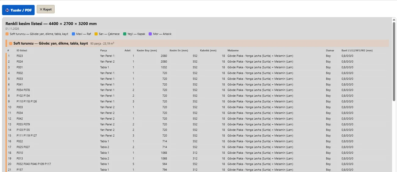
A side panel that should finish at 720 mm, with 2 mm banding on both ends, comes out at 724 mm if it is cut at 720, and the cabinet will not go together. Edge banding, the PVC or similar strip glued to a part's visible edge, directly affects the cut size. In the program's Production Settings you decide how it is handled: with Net selected the band thickness is subtracted from the cut size; with Gross it is not. You set band thickness separately for carcass, doors and hidden edges, and you enter once, in Workshop Standards, the thickness below which thin banding is not subtracted.
Some materials have no banding at all: membrane wraps the edge, lacquer paints it, and on solid wood or compact board the edge is the material itself. The program knows this and leaves banding out of the cut list. Hidden edges on fillers, plinths and crown pieces also come through unbanded. Each part's banding is shown in its own column for each of the four edges, so the person on the edge bander reads the list instead of guessing.
These options behave like a dynamic settings page: a value you change in Production Settings flows into the outputs of the open project, the screen tells you how many settings differ from the defaults, and ↺ Reset to default takes you back. The Standard, Kitchen 32 mm and Batch production presets load with one click.
Why does grain direction matter in sheet layout?
If one door on a woodgrain melamine kitchen comes out with vertical grain and its neighbour with horizontal grain, the job never looks finished. Grain direction, the direction in which the pattern runs across the sheet, decides whether a part may be rotated during nesting. In the program's router layout doors are never rotated; the pattern direction is preserved. A door wider than the sheet is laid flat only when it would not fit any other way. If you want to gain space on a plain, patternless board, you can turn on Free direction in the Cutting Plan window, and parts may then rotate 90°.
Every row of the cut list has a grain column, and the grain is printed on the part label as well. Whoever picks the part up after cutting can see from the label which way to turn it on the bander or during assembly.
How does sheet nesting reduce waste?
Sheet nesting means arranging parts on the sheet with as little waste as possible. The program's router layout leaves exactly one cutter diameter between parts: the toolpaths of two neighbouring parts share the same channel and never cut into either part. If your shop wants more clearance, simply enter a slightly larger cutter diameter. The nesting engine tries many criteria and sort orders, puts the panel-saw cutting plan into the race as a candidate, and picks the result that uses the fewest sheets; on a tie it gathers the remainder into one large offcut. The same design always produces the same layout.
The resulting automatic sheet layout, the drawing that shows which part lands where on which sheet, appears in the Router layout preview in the CNC step and in the Cutting Plan window. In the Cutting Plan you enter sheet size, blade kerf, trim and number of sets; the sheet summary reports sheets per material, the fill of full sheets and of the last sheet separately, and the waste in m². Small parts that might slide on a vacuum table are listed separately too; you set the threshold in the "Small part limit (mm)" field.
In what order does the NC program cut?
This is where CabinetWizard's own CNC cutting and machining system comes in: a setup that produces one NC program per sheet straight from the design, with no separate toolpath calculation. When you press "CNC Router — NC (G-code)" in the CNC step, a .zip downloads containing one program per sheet plus a README file. Each program runs in this order:
- Drilled holes first: shelf pin holes and hinge plate holes.
- Then larger holes with the cutter: blind ones as pockets (for example the Ø35 hinge cup), through ones as helical cuts (tap, drain, cable grommet).
- Outside contours last, from the smallest part to the largest; cutter offset outside, multiple passes, with a small plunge into the spoilboard.
Leaving the contour for last is deliberate: every hole is in before the part separates from the sheet. For small parts you can switch on an onion skin pass: the contour is cut leaving a thin skin of material, and that skin is removed in a separate section at the end of the sheet. A part whose holes are on the underside is machined flipped. Work the machine cannot do is never silently skipped; it is written into the README as manual work.
Where a column or beam meets a cabinet, the carcass is notched in place, and in kitchens the back panel is cut where it meets a service point. These notches and cut-outs go to the NC and DXF files with the same dimensions.
What are the Machine Profile and Tool Library for?
Every shop has its own cutters, drills and habits. The Tool Library comes with default tools such as end mills, drills and V-bits; diameter, pass depth and feed are your values, and they are saved. The Machine Profile defines the format of the generated code; the program writes generic ISO G-code. The important part: the program reads the generated code back and checks it, and if there is an error no file is produced. For a profile not yet verified you get a test program and a checklist; we recommend verifying the first job on your machine with a test piece.
If you machine patterned doors, you pick or draw the pattern in the Part Machining screen; the pattern is carved first and the contour cut last. Ready-made patterns fit the door's size whatever door style you choose. For the full kitchen workflow, see our article on making a kitchen design CNC-ready.
Should I send DXF or NC?
If your machine reads G-code directly, use the NC package. If you drive the machine through your own CAM software, the separate program that calculates toolpaths, the DXF output opens there. The program's CNC/DXF output comes in two forms: a combined DXF and a per-part DXF (.zip). In the per-part files the contour, info and hole layers are separate; hole layers carry the hole type and the face name, so the operator can machine the two faces separately. The hole table downloads as CSV too.
Whichever you choose, "export to CNC" no longer means retyping a list: the export is made from the design itself. In the CNC cabinetmaking chain there is no step left where a size is copied by hand.
What happens when the customer changes a size?
If the job is already being cut and the customer says "let's make the unit next to the fridge 50 mm narrower", you do not recut the whole kitchen. The program identifies the changed parts and lists only those; the cut list, sheet layout, NC and labels are produced for that subset. A part that merely moved without changing size is not recut. If a part breaks during assembly, you find it by its code, its P number or the QR code text on its label, mark it "Broken" and send it back to cutting.
Before any production output, the program asks for a confirmation: you tick that you will check every size, quantity and layout yourself. When the design changes, that confirmation drops. This small step keeps an old printout from getting mixed up with a new design.
What does this approach give the shop?
Accurate cutting is also time-saving cabinet design: you enter a size once and the list, plan, labels and program all follow from it. The claim on our home page, "go from design to the CNC cutting file in 15 minutes", is the result of that chain. Fast cabinet design only helps when the production data behind it is right; otherwise speed just makes mistakes happen faster.
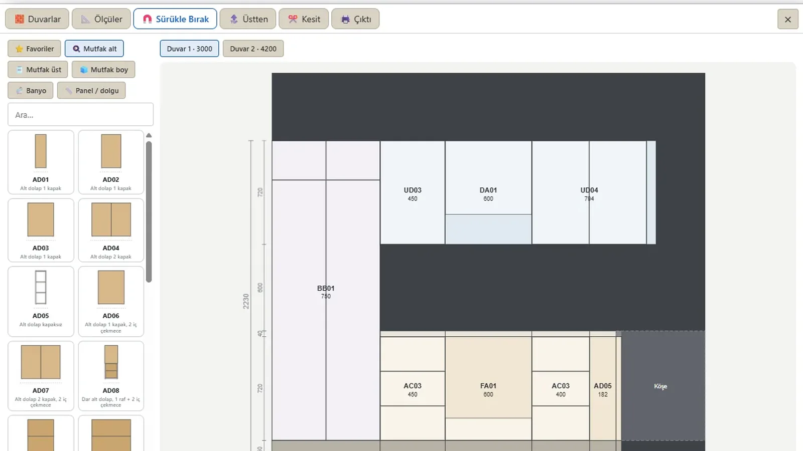
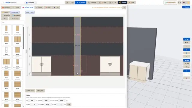
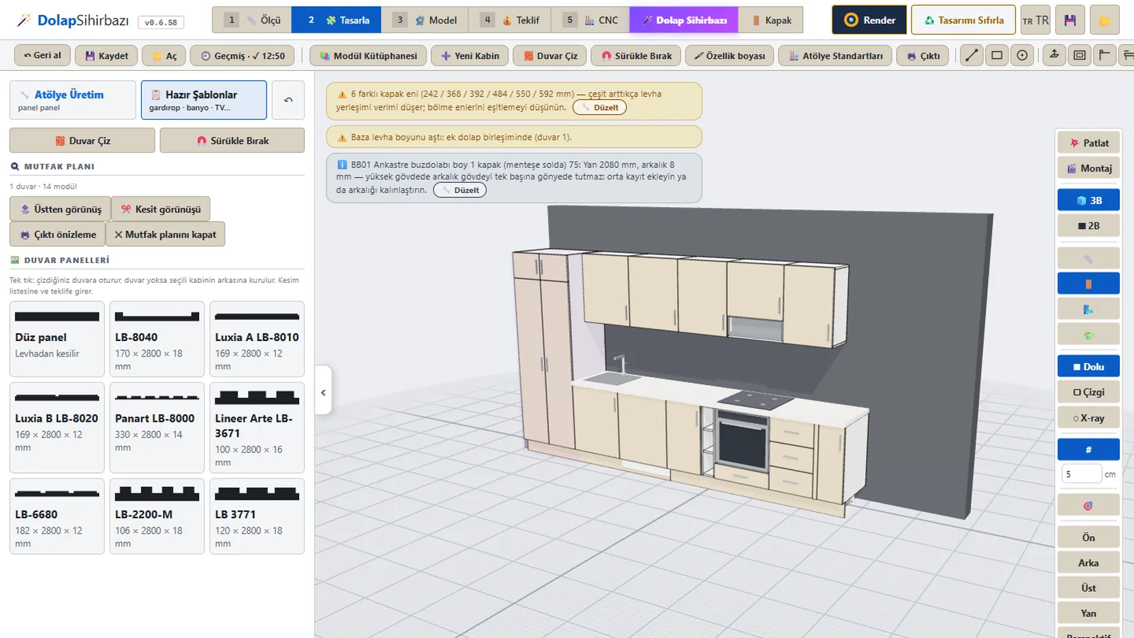
The program designs kitchens as well as wardrobes and closets. For kitchen cabinetry design you use drag-and-drop modules, ready base, wall and tall units that you drop from a palette onto the wall; there are 245 ready modules and 386 door designs. Changing a door, a handle or a material, in other words a finish change, does not touch the sizes; with the Property painter you transfer one cabinet's door, handle, banding and material to others with a click. When you change a dimension the doors and parts update together, which is what we call dynamic kitchen design. Planning where cabinets place themselves around the door swing, the services and the columns is what we call smart kitchen design: Auto Place puts the sink at the drain and the hob at the gas, and no cabinet goes where a door swings.
In short, the program works as your own cabinet design studio: design, automatic cut list, layout, NC and quote in one window. In the quote, every price comes from the unit prices you enter. For the program's current price and launch terms, see the pricing section. We explain how the cut list, CNC and rendering come together in one program in this article. Every cabinet follows the same path.
Frequently asked questions
Which CNC machines does it work with?
The program produces generic ISO G-code and DXF. You need to know whether your machine reads that code directly or whether you open the DXF in your CAM software. Verify the first job with a test piece.
Can I get a cut list in the demo?
No. In the free 5-day demo, design, 3D and rendering are open; production outputs such as the cut list, cutting plan, NC, DXF, labels and quote are in the full version.
What is printed on a part label?
Labels print at 50 × 30 or 70 × 40 mm and include the part, size, banding diagram, grain and a QR code. The fitter sees from the label which cabinet the part belongs to.
Can I change the sheet size?
Yes. You enter sheet length and width per material, add offcuts to stock and deduct them from stock after cutting.
By Ufuk Şen, developer of CabinetWizard